|
Cockpit component placement, holes and cutouts
|
| Click image to enlarge |
|
| Click image to enlarge |
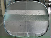
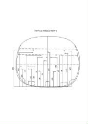
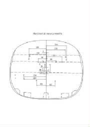
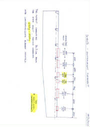
These pictures and drawings show where to drill holes and cut
openings for installing the flap handle, elevator trim knob slider, and throttle-choke assembly in the cockpit.
The pictures show the jigs that the factory uses to quickly guide the drill for mounting holes. I used a combination
of the dimensions, paper templates made from the drawing dimensions, and match drilling to the components themselves.
Flap Handle
|
| Click image to enlarge |
This is a correction to the flap handle installation drawing
in the kit manual. The correction is that the two angle brackets at the aft end of the assembly should point forward.
The earlier version of the drawing had them rotated 180 degrees from this.
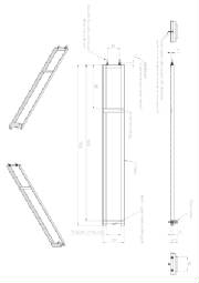
Rudder Bracket Jig
|
| Click image to enlarge |
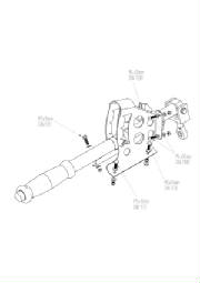
This is a detail drawing of the factory jig used to install the upper
rudder support bracket. The two pins go into the same holes in the lower rudder control arm that the rudder plugs into.
The distance between the lower pins and the upper cross piece matches the rudder itself, to position the upper support and
its hinge correctly. The washers and nuts on the lower pins allow the jig to clear the bolt in the center of the control
arm. There are other ways to do this, but I just copied the design and dimensions of the factory jig, because it
was pretty easy to do.
When I'm done with the jig in a few days, I'm willing to loan it out to other
builders if you don't want to build your own. Just contact me through the Pipistrel on-line forum.
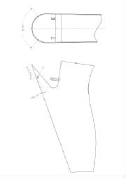
Tail Wheel Spring Connection
|
| Click image to enlarge |
|
| Click image to enlarge |
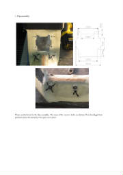
These drawings show the assembly of the parts that attach the
tail wheel springs to the rudder, and the positions of the attachment holes in the bottom of the rudder.
Supplemental fuel system photographs
These photos from Tomaz provide some supplementary detail on the
routing and connection of the fuel lines, and show the location for the hole in the lower firewall.
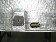
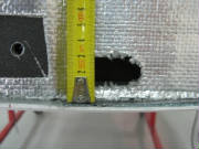
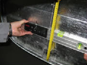
Firewall penetration details
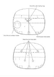
These photographs and drawings show the location and size of
the various firewall openings. The numbers on the photos indicate the hole sizes (in millimeters). Tomaz advises
to drill these holes when they are needed, rather than all at once. He also cautions to check the cabin heating valve
position to ensure that it does not interfere with the electrical panel that mounts on the aft side of the firewall.
Pipistrel
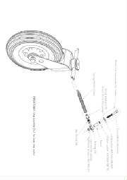
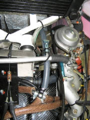
Factory photos of Rotax engine modifications and installation
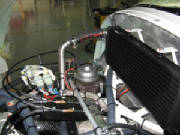
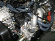
The photographs below show how the factory supports the engine
by bolting the propeller flange to a heavy metal structure. They can then rotate the engine around the crankshaft to
easily access both the top and the bottom of the engine.
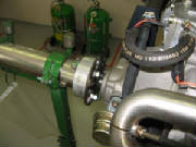
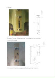
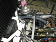
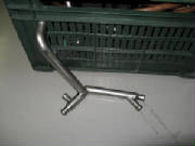
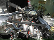
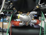
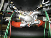
Here are pictures of the water manifold tubing assembly and
its installation. The water manifold tubing replaces the water connection box mentioned in the kit manual.
Just below the center of this picture is the water hose flange.
It appears identical with the flange and elbow installed on my engine, although the kit manual contains photographs that make
it appear that one or another of these flange assemblies is modified. I'll see how it works out as I proceed, but
for now I don't see the need to change anything here.
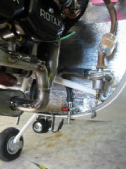
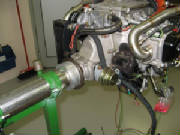
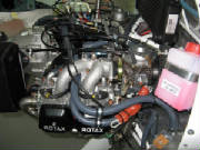
Here are two photographs of the engine installed on the plane at
the factory.
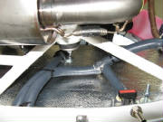
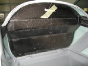
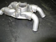
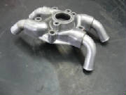
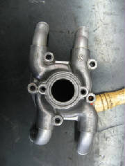
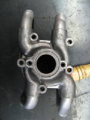
Here are several photographs showing details of the modified
water pump housing showing the repositioning of the elbows that are screwed into the water pump housing. Also,
one of the elbows originally attached to the housing is replaced with a different elbow supplied with the kit.
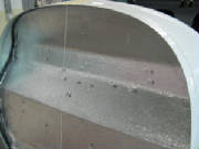
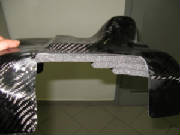
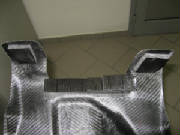
Here are two photos that clarify the installation of adhesive-backed
foam to the carbon fiber cooling air duct.
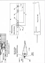
Aileron counterweight placement
The drawing below provides supplemental detail on the placement of
the aileron conterweights.
|